
Comparator
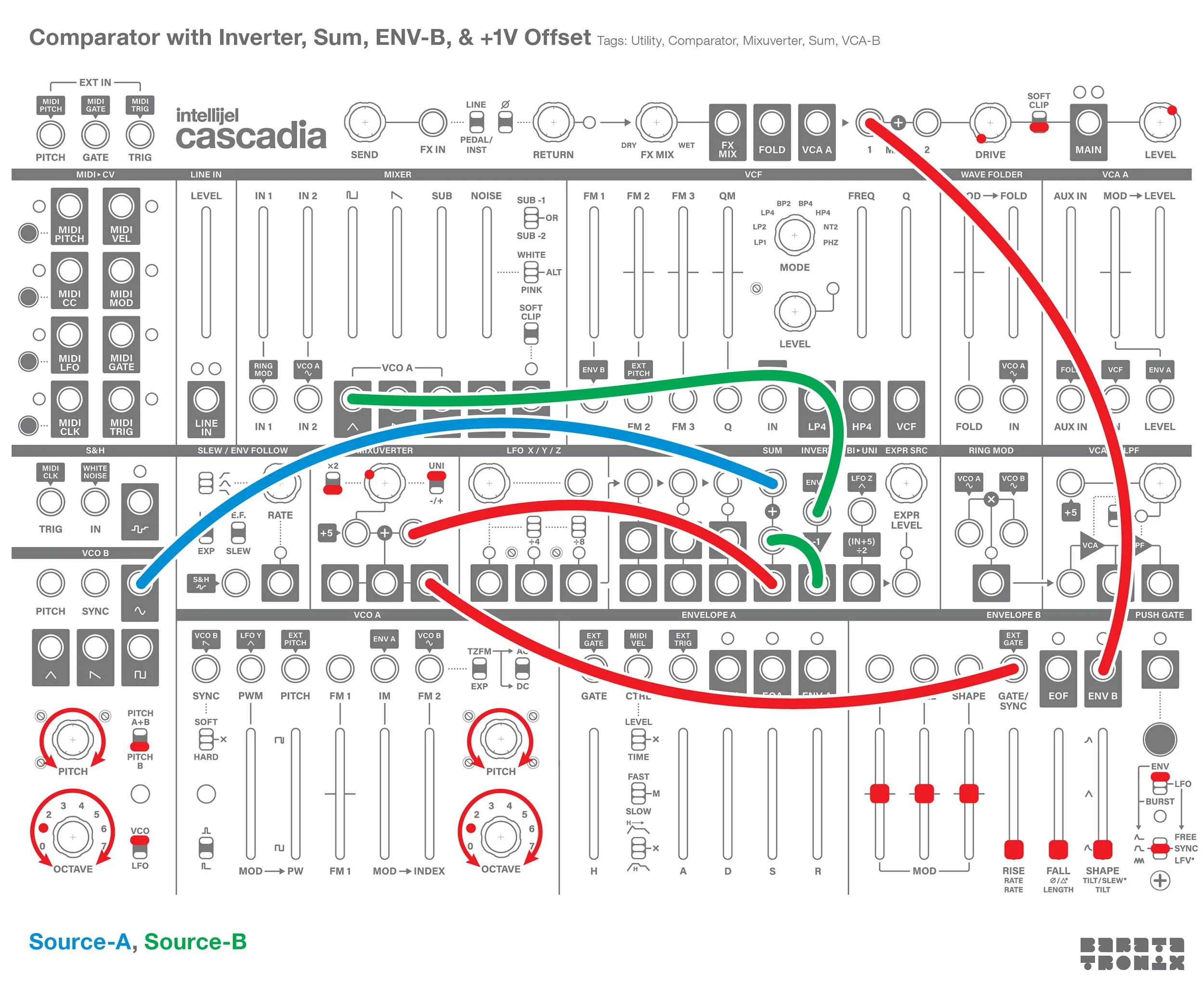
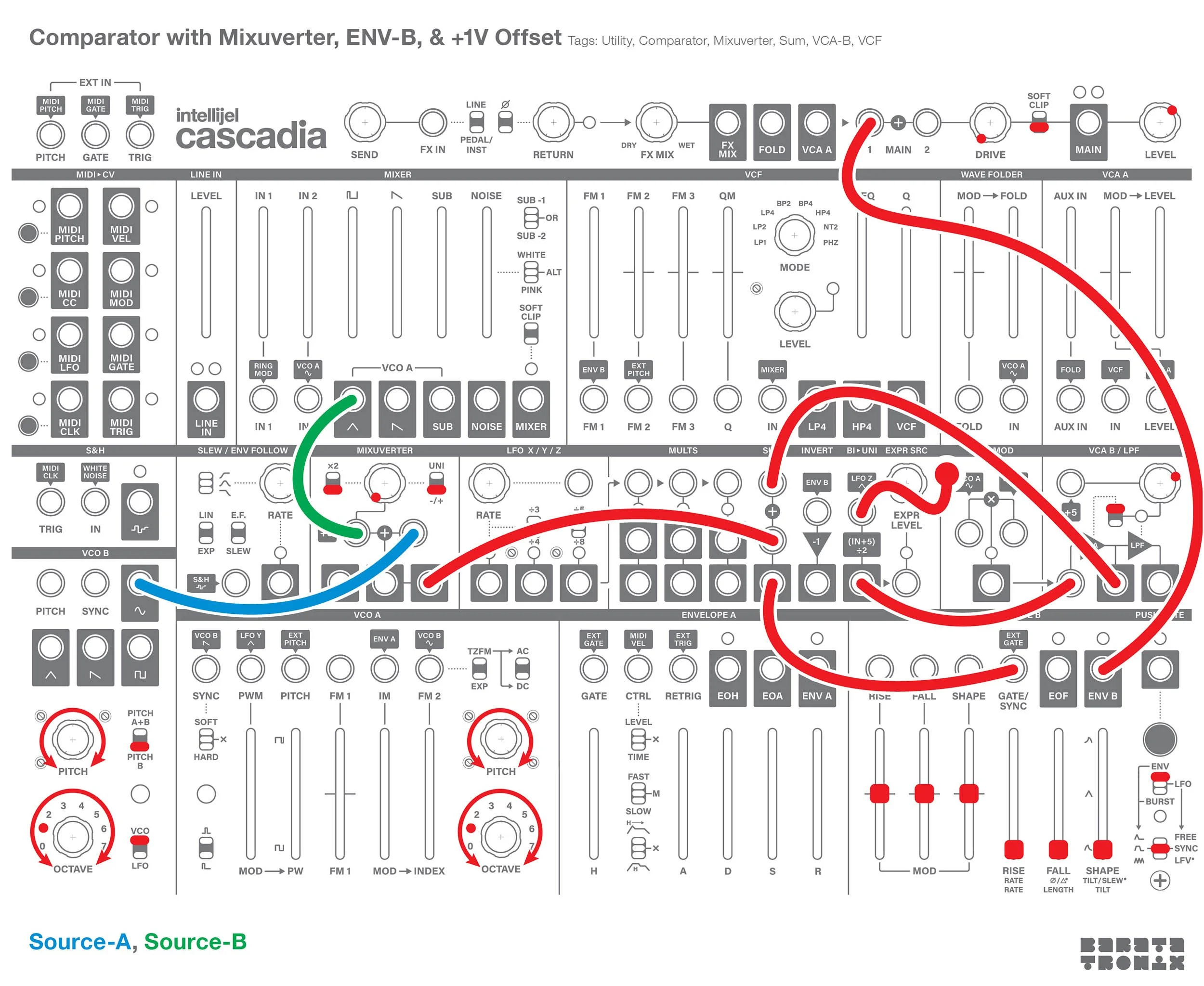

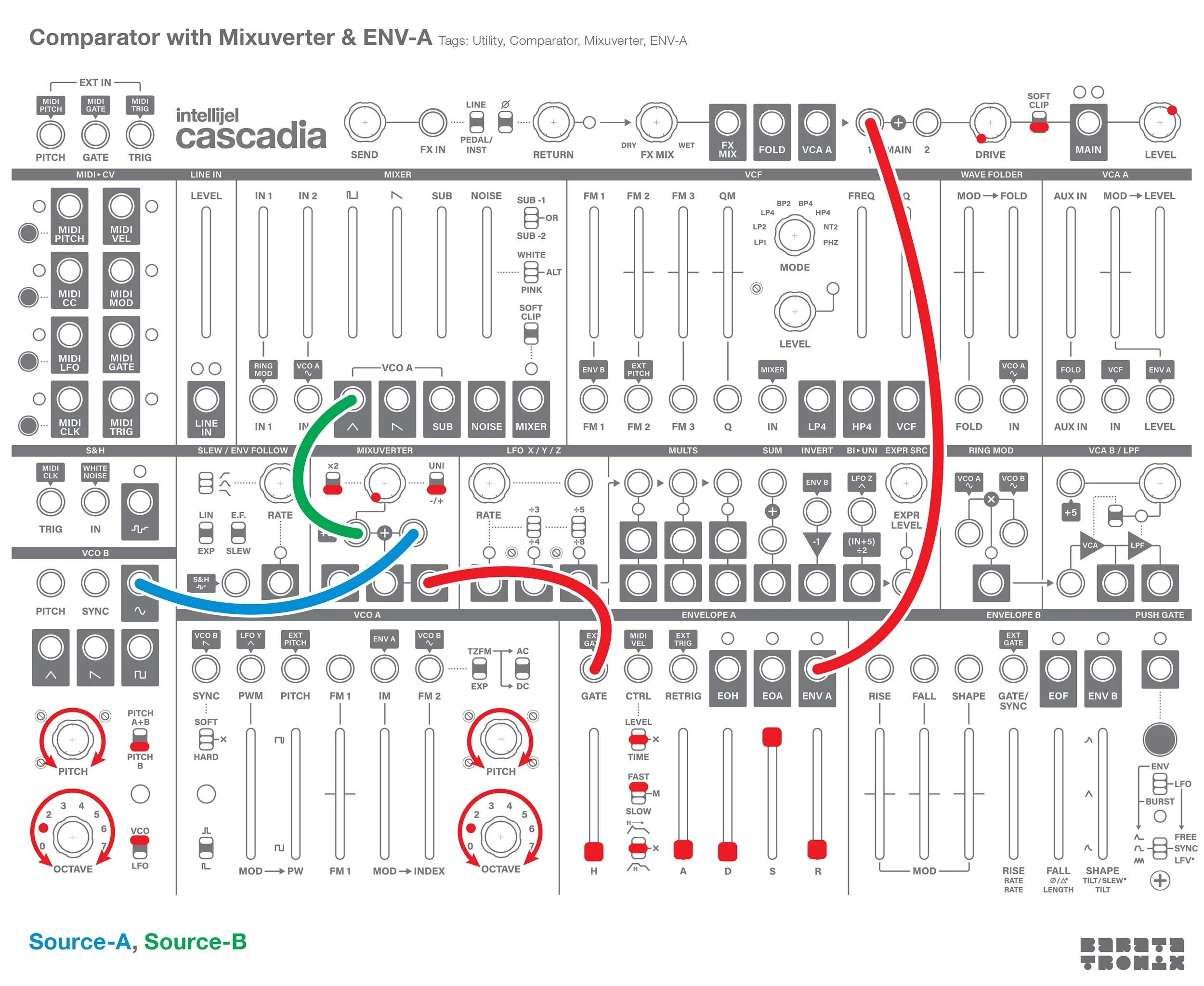
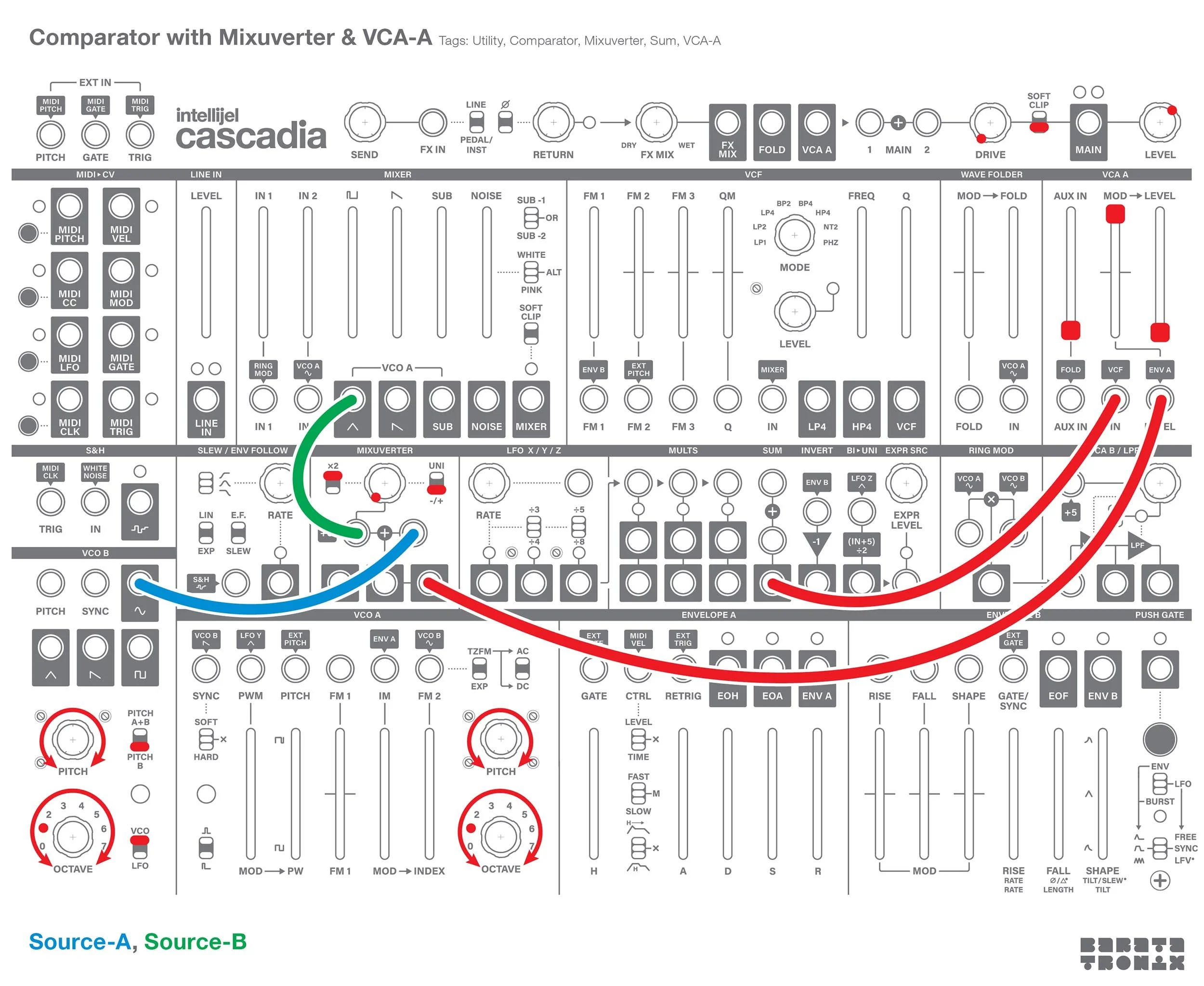
A comparator compares two input voltages and outputs a binary high/low signal indicating which has the higher voltage. You can use a comparator to convert a signal to a pulse wave, extract rhythmic gates from signals, trigger events when an envelope reaches a specific height, as part of a larger logic operation, generating a fuzz box, etc.
A comparator has two inputs (A and B), and a binary output (high/low). Input B can be either a constant threshold, or a variable signal. If the voltage of A is greater than B, the comparator outputs a high signal (+5V). If the voltage of A is less than B, the comparator outputs a low signal (0V).
You can build a comparator by finding the difference between two signals, then converting the result into a binary output. This can be done by performing the following operation on a signal: Output = true if (A - B) > 0, else Output = 0. Where A is the main signal and B is the threshold.
None of these options will produce a perfect comparator, but depending on your needs, they might be good enough.
Comparing Two Dynamic Signals:
Difference:
Compare two voltage sources and output a pulse only when signal A is higher than signal B.
Mixuverter Based:
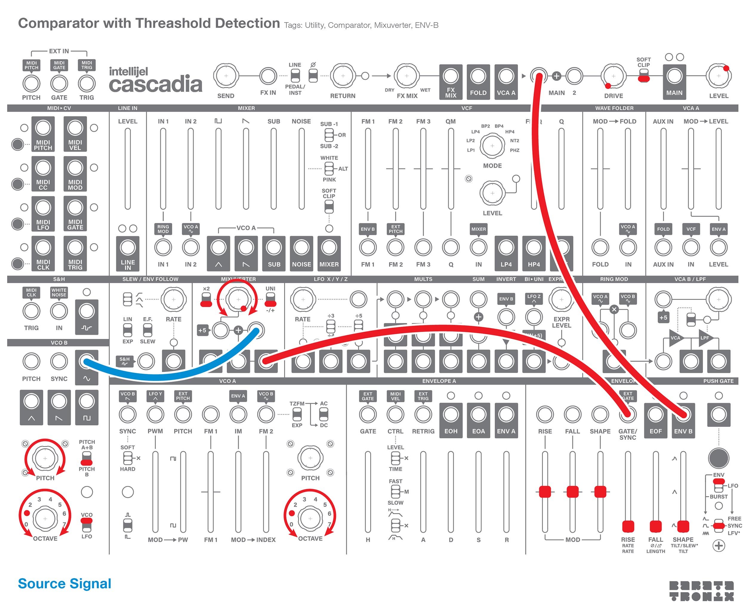
Set the mixuverter’s 2x switch to the down position.
Set the mixuverter’s polarity switch down to the bipolar position.
Patch the source signal to the mixuverter’s secondary input (the one on the right).
The attenuator sets the comparator’s threshold.
The mixuverter output is the difference signal. It now needs to be converted into a binary on/off gate.
1V Offset
The easiest way to convert mixuverter’s output into a binary on/off gate is with either of the envelopes.
However, there is one caveat, the envelope’s gate triggers at +1V rather than 0V.
If you patch the mixuverter’s output directly to either envelopes gate, the comparator output will sometimes come in late. If you need the timing to be more correct, you can fix this with a +1V offset, or you can skip this step and patch from the mixuverter directly to one of the envelope gate inputs.
Break the bipolar to unipolar converter’s normalled input by patching a dummy (unpatched at the other end) cable into the bipolar to unipolar converter. The Bi>Uni will output a 2.5V reference signal if you patch a dummy cable into its input. The Bi>Uni adds 5V to whatever is patched into it, then divides the result in half.
If the input is 0: (0 + 5) / 2 = 2.5.
Patch the Bi>Uni out to the VCA-B audio in. The VCA can be used to scale the Bi>Uni signal down to +1V.
Set the VCA-B control switch up.
Patch the VCA-B out to one of the envelope’s gate inputs.
Turn the VCA CV amount knob fully clockwise, then turn it up until the envelope fires.
Unpatch the VCA output from the envelope, and now patch it to one of the sum inputs.
Patch the mixuverter’s output to the other sum input.
Patch the sum out to one of the envelope gate inputs.
Binary Output:
Either envelope can be used to generate the binary gate.
ENV-A:
Set the CTRL source switch to the centre (X) off position. You don’t want velocity to have any effect on the level or length of the envelope.
Set the time switch to fast. At slower speeds there will be a short transition time even when the attack and decay sliders are all the way down. At the fast speed it can generate a pulse with a near immediate attack and decay.
Set the attack, decay, and release sliders all the way down.
Set the sustain slider all the way up.
ENV-B:
Set the mode to envelope.
Set the type to AHR.
Pull the rise, fall, and shape sliders all the way down.
The envelope’s output will be the comparator’s output.
Inverter and Sum Based:
Alternatively, you can replace the mixuverter with the inverter and sum utilities.
Patch signal A to one of the sum inputs.
Patch signal B to the inverter.
Then, patch the inverter to the other sum in. The sum out is now A + -B = A - B.
The sum output is now the difference signal. It now needs to be converted into a binary on/off gate.
1V Offset
As with the mixuverter based comparator patch, you need to add a +1V offset for the most accurate timing.
Set the mixuverter’s 2x switch to the down position.
Set the mixuverter’s polarity switch up to the unipolar position.
Patch from the mixuverter to an envelope gate in.
Turn the mixuverter attenuator knob fully counterclockwise and slowly raise it until the envelope triggers.
Patch from the sum out to the mixuverter’s secondary input. This signal will be summed with the attenuator value, offsetting the the signal. 0V from the different signal should now trigger the envelope.
Binary Output:
Setup the selected envelope the same as with the mixuverter based patch above.
Comparing a Signal Against a Constant Voltage:
This patch compares a source signal against a constant threshold voltage. As long as the source signal is above the threshold voltage, a high gate will be output. If the source signal is below the threshold voltage, 0V will be output.
Mixuverter:
Set the mixuverter’s 2x switch to the down position.
Set the mixuverter’s polarity switch down to the bipolar position.
Patch the source signal to the mixuverter’s secondary input (the one on the right).
The attenuator sets the comparator’s threshold.
Setup the offset and envelopes as with the previous examples.
Generating Pulse Signals from VCA-A
Another option is to generate a pulse signal by hard clipping the difference signal into a half-wave rectifier. You can do this on Cascadia with VCA-A. The VCA’s CV input will act like a half-wave rectifier and cut off everything below 0V. Everything above the +5V reference voltage will be cut off. The 2x scaling of the mixuverter’s signal will create a hard clipping like effect.
Use the mixuverter to get the difference between two signals as described above.
Set the mixuverter’s 2x switch to the up position. The signal will no be scaled by 2.
Patch from the mixuverter to VCA-A’s CV/level in.
Push VCA-A’s mod slider fully up, and pull the level slider fully down.
Patch from the sum out to VCA-A’s audio in. The sum’s first input (top) is normalled to +5V. If nothing is patched into the sum you can use it as a constant +5V reference voltage.